ESP32的VSPI和HSPI

说明
SPI共有4根线,MOSI、MISO、CS、CLK,在ESP32中对应规则如下表:
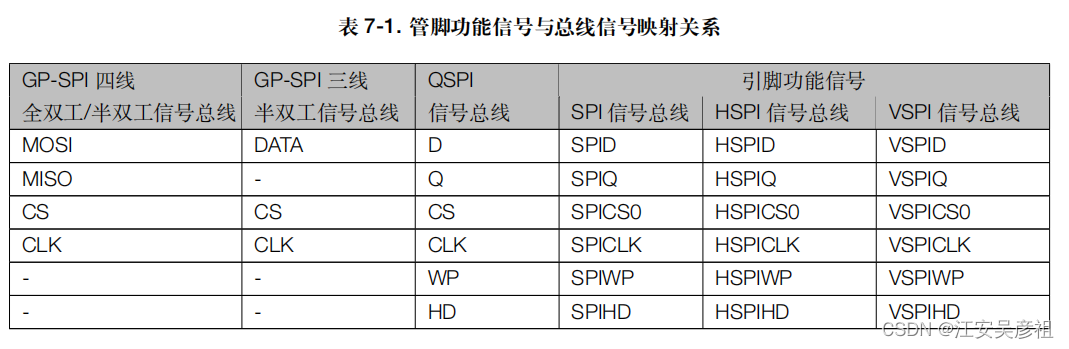
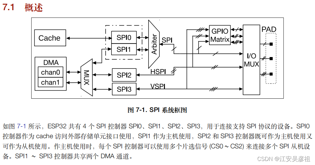
ESP32共有4个SPI,但是用户能够使用的只有2个SPI,分为VSPI和HSPI。
引脚接口
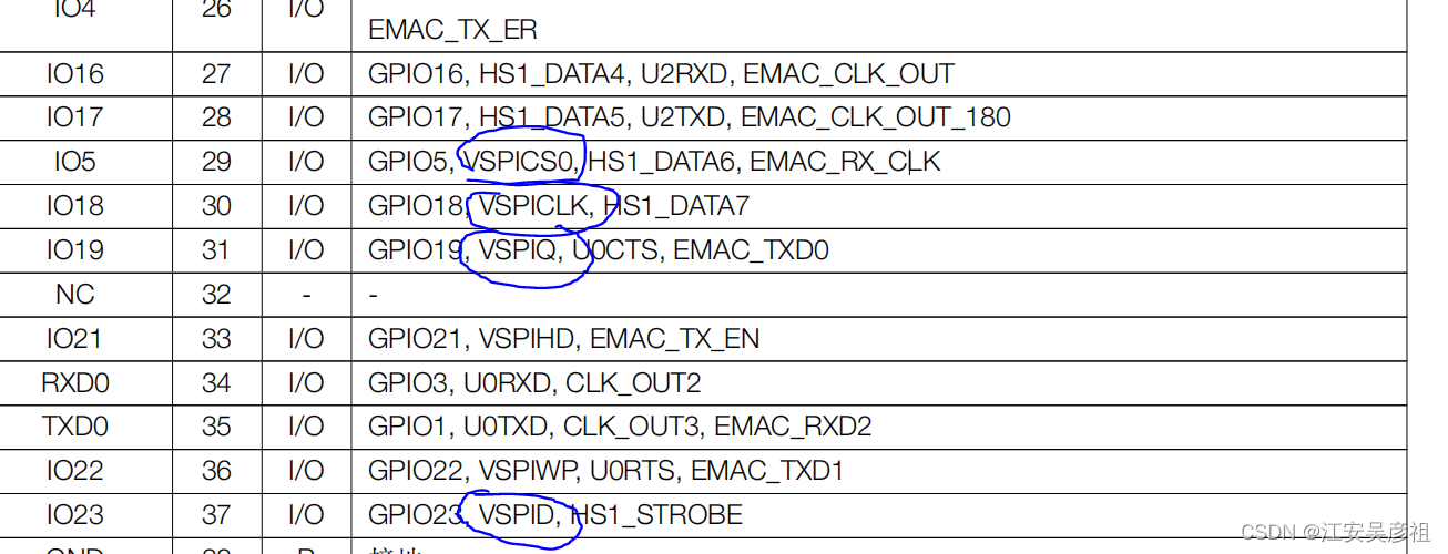
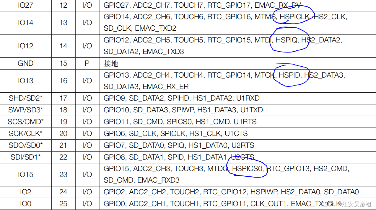
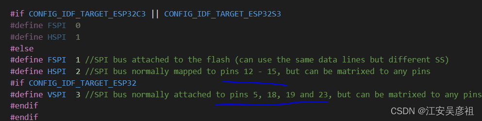
在ESP32的数据手册中,说明了VSPI和HSPI对应的引脚:
- VSPI:
- HSPI:
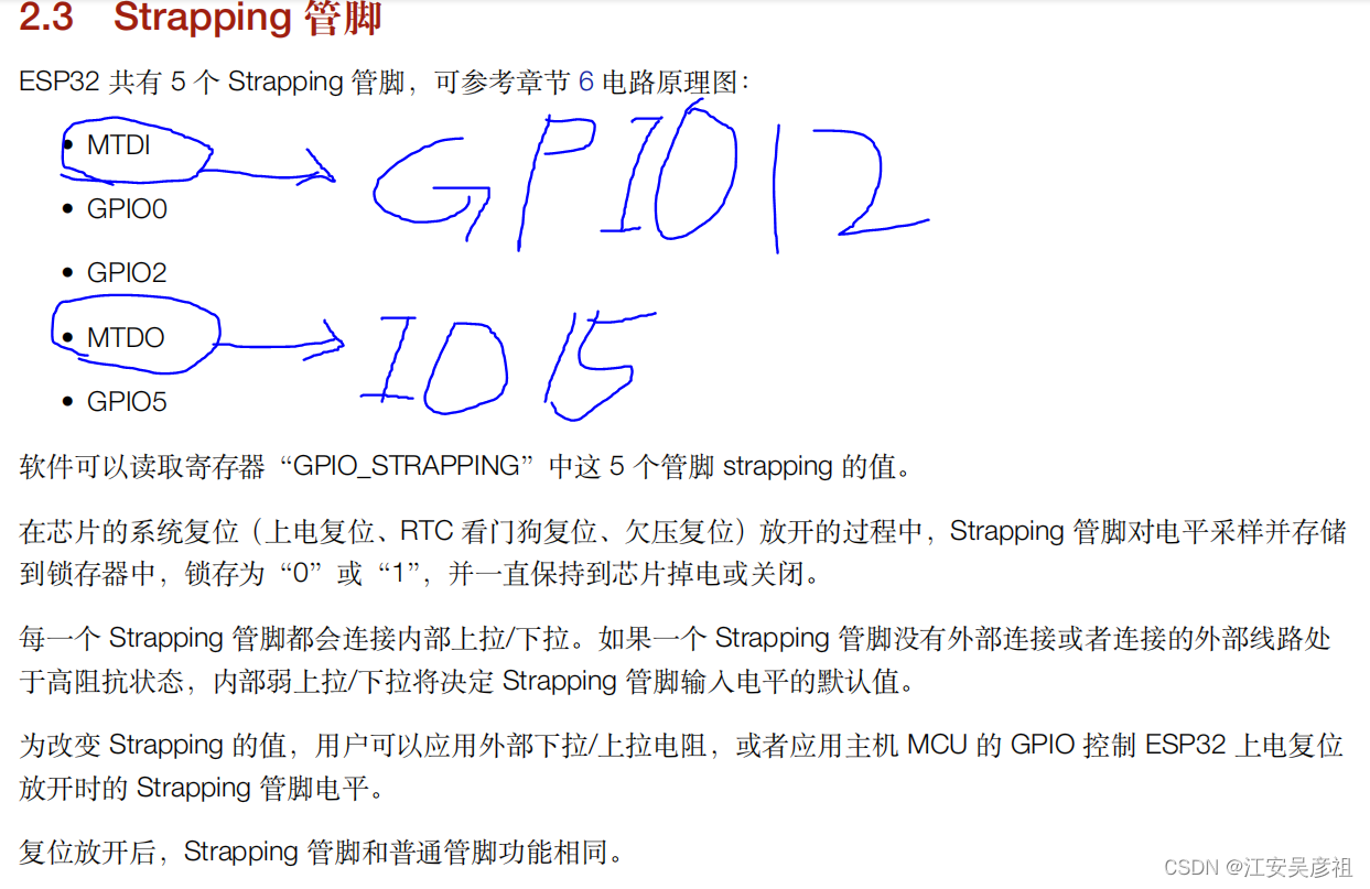
但是比较麻烦的是,ESP官方不知道犯了什么SB毛病,非弄出来个没有丝毫用途的Strapping 管脚,稍不注意,上电瞬间Strapping管脚电平不对,就没法正常启动,导致但凡是有Strapping管脚功能的引脚,大家都不敢使用。
在SPI中也是这样,VSPI和HSPI默认的引脚中,都有作为Strapping管脚的引脚。我们要格外格外的小心。
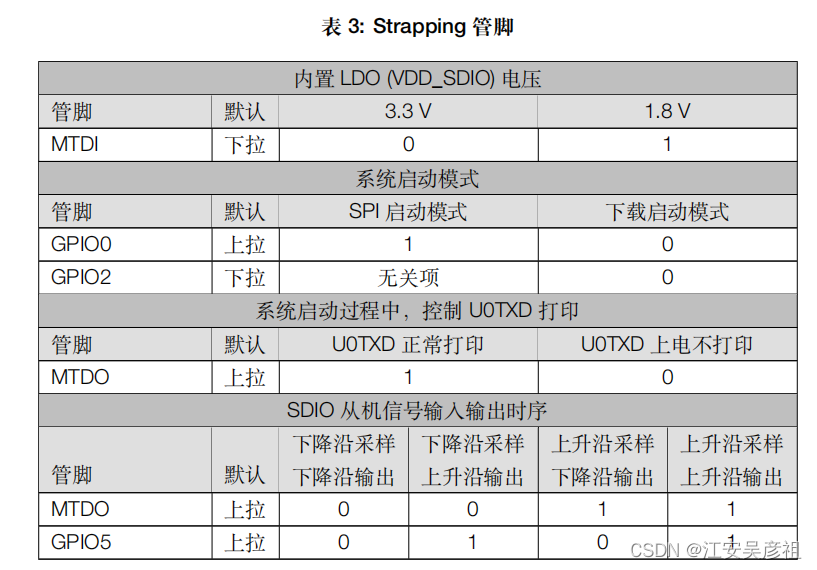
结合Strapping管脚,将引脚对应整理如下表:
- VSPI
| 引脚 | 功能 | 备注 |
|---|---|---|
| IO23 | MOSI | |
| IO19 | MISO | |
| IO18 | CLK | |
| IO5 | CS | Strapping管脚,上电瞬间必须保证上拉 |
- HSPI
| 引脚 | 功能 | 备注 |
|---|---|---|
| IO13 | MOSI | |
| IO12 | MISO | Strapping管脚,上电瞬间必须保证下拉 |
| IO14 | CLK | |
| IO15 | CS | Strapping管脚,上电瞬间必须保证上拉 |
更改Auduino框架中SPI默认的引脚
在用arduino框架时,其默认的SPI引脚如下:
除了使用默认的引脚之外,还可以使用其他方式更改默认引脚。官方给出的示例如下:
/* The ESP32 has four SPi buses, however as of right now only two of* them are available to use, HSPI and VSPI. Simply using the SPI API * as illustrated in Arduino examples will use VSPI, leaving HSPI unused.* * However if we simply intialise two instance of the SPI class for both* of these buses both can be used. However when just using these the Arduino* way only will actually be outputting at a time.* * Logic analyser capture is in the same folder as this example as* "multiple_bus_output.png"* * created 30/04/2018 by Alistair Symonds*/
#include <SPI.h>// Define ALTERNATE_PINS to use non-standard GPIO pins for SPI bus#ifdef ALTERNATE_PINS#define VSPI_MISO   2#define VSPI_MOSI   4#define VSPI_SCLK   0#define VSPI_SS     33#define HSPI_MISO   26#define HSPI_MOSI   27#define HSPI_SCLK   25#define HSPI_SS     32
#else#define VSPI_MISO   MISO#define VSPI_MOSI   MOSI#define VSPI_SCLK   SCK#define VSPI_SS     SS#define HSPI_MISO   12#define HSPI_MOSI   13#define HSPI_SCLK   14#define HSPI_SS     15
#endif#if CONFIG_IDF_TARGET_ESP32S2 || CONFIG_IDF_TARGET_ESP32S3
#define VSPI FSPI
#endifstatic const int spiClk = 1000000; // 1 MHz//uninitalised pointers to SPI objects
SPIClass * vspi = NULL;
SPIClass * hspi = NULL;void setup() {//initialise two instances of the SPIClass attached to VSPI and HSPI respectivelyvspi = new SPIClass(VSPI);hspi = new SPIClass(HSPI);//clock miso mosi ss#ifndef ALTERNATE_PINS//initialise vspi with default pins//SCLK = 18, MISO = 19, MOSI = 23, SS = 5vspi->begin();
#else//alternatively route through GPIO pins of your choicevspi->begin(VSPI_SCLK, VSPI_MISO, VSPI_MOSI, VSPI_SS); //SCLK, MISO, MOSI, SS
#endif#ifndef ALTERNATE_PINS//initialise hspi with default pins//SCLK = 14, MISO = 12, MOSI = 13, SS = 15hspi->begin();
#else//alternatively route through GPIO pinshspi->begin(HSPI_SCLK, HSPI_MISO, HSPI_MOSI, HSPI_SS); //SCLK, MISO, MOSI, SS
#endif//set up slave select pins as outputs as the Arduino API//doesn't handle automatically pulling SS lowpinMode(vspi->pinSS(), OUTPUT); //VSPI SSpinMode(hspi->pinSS(), OUTPUT); //HSPI SS}// the loop function runs over and over again until power down or reset
void loop() {//use the SPI busesspiCommand(vspi, 0b01010101); // junk data to illustrate usagespiCommand(hspi, 0b11001100);delay(100);
}void spiCommand(SPIClass *spi, byte data) {//use it as you would the regular arduino SPI APIspi->beginTransaction(SPISettings(spiClk, MSBFIRST, SPI_MODE0));digitalWrite(spi->pinSS(), LOW); //pull SS slow to prep other end for transferspi->transfer(data);digitalWrite(spi->pinSS(), HIGH); //pull ss high to signify end of data transferspi->endTransaction();
}