手势控制的机器人手臂

将向你展示如何构建机械手臂并使用手势和计算机视觉来控制它。下面有一个在开发阶段的机械手臂的演示视频。
展示开发中的手臂的演示视频:https://youtu.be/KwiwetZGv0s
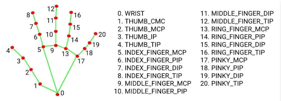
如图所示,该过程首先用摄像头捕捉我的手及其标志。通过跟踪特定的界标,例如拇指和食指的指尖,可以确定这些界标的相对运动,并将其转化为伺服系统的运动。这是通过处理数据并将整数值发送到控制伺服电机的 Arduino 的 Python 脚本完成的。
操作流程:
相机 —> python 脚本 —> Arduino —> 伺服电机
此项目的项目列表
-
机械臂套件(仅限框架和伺服电机 (MG996)):
-
Arduino 板(加 USB 线)
-
跳线
-
电话充电器
-
PCA9685 伺服电机驱动器
-
笔记本电脑
-
抽吸泵套件:
-
继电器模块
使用的编程环境:
-
开发环境
-
PyCharm 编辑器
先决条件:
-
OpenCV 知识
-
youtube 上有教程:https://www.youtube.com/watch?v=WQeoO7MI0Bs&t=8774s
-
-
了解 C++ 和 Python
需要修改机械臂组件(用于我购买的套件),因为伺服电机在完全组装后无法移动机械臂,导致某些自由度 (DOF) 的损失,并取消了作为末端执行器的抓手。我选择改用抽吸泵机构。
对于这个项目,你可以只购买我使用的机械臂套件,或者只购买底盘并升级到更强大的伺服系统,以与完整的组件一起工作。第二种选择需要你使用本文作为指导,并进行修改以达到你想要的结果。
-
组装机械臂:
-
将 Arduino 代码加载到电路板上,并使用电路图连接伺服电机。
-
是时候组装机器人手臂了。在开始之前,确保按照此处所述(https://www.electroniclinic.com/pca9685-servo-driver-arduino-circuit-diagram-and-code/#google_vignette),通过下载并安装 HCPCA9685 库来加载 Arduino 代码。使用提供的电路图连接伺服电机,以确保它们处于所需位置。首先将手臂底部的伺服(旋转底座关节)连接到 PCA9865 的引脚 0,然后将手臂中的下一个伺服(肩关节)连接到引脚 3,依此类推,从左到右移动 PCA9685。最后,启动 Arduino 板并等待伺服电机到达其位置。
-
手臂关节
-
将滑轮放在伺服电机上并固定螺钉。
-
现在是时候组装机器人手臂的其他部分了。使用此处(https://automaticaddison.com/how-to-build-a-diy-aluminium-6-dof-robotic-arm-from-scratch/) 链接的视频作为指南,但你可以随意使用自己的方法来实现图像中描绘的姿势。如果在测试过程中遇到任何问题,例如关节不动,请检查伺服电机是否发热。如果天气很热,则该接头处可能存在装配问题,导致其无法正常工作。
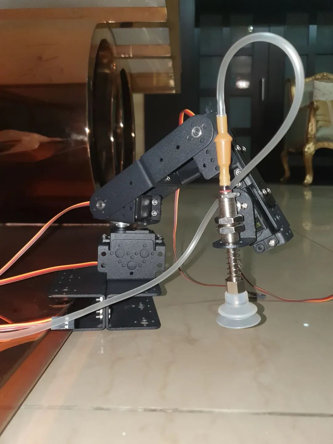
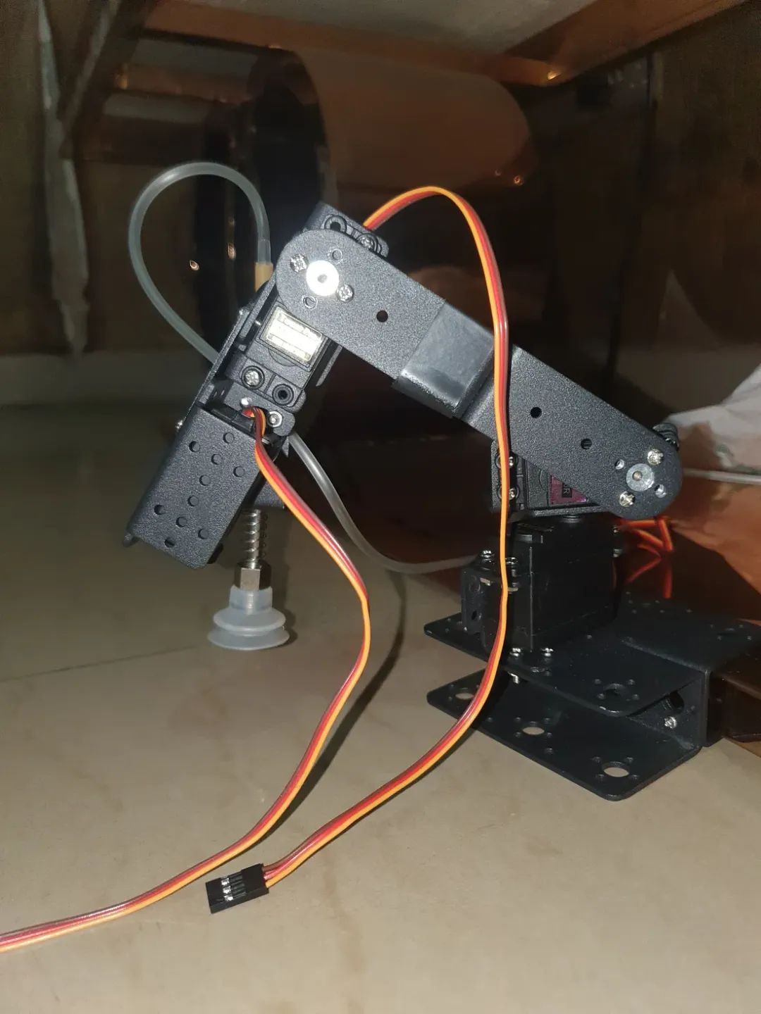
图片显示机器人手臂处于原位。
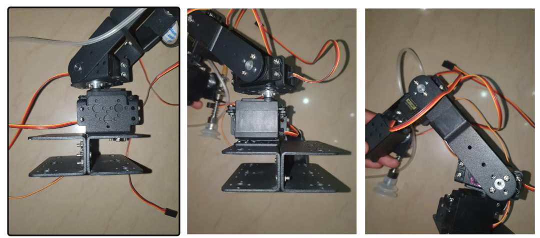
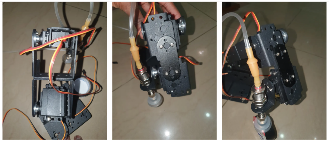
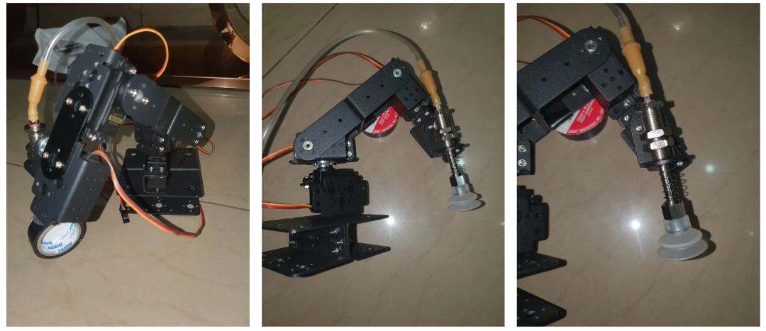
组装手臂时供参考的附加图片
-
连接抽吸泵:
-
如下图所示连接软管,黑色箭头代表空气的连接和流动。
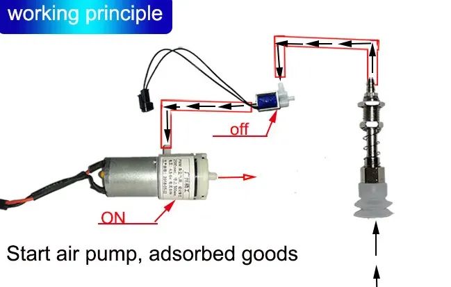
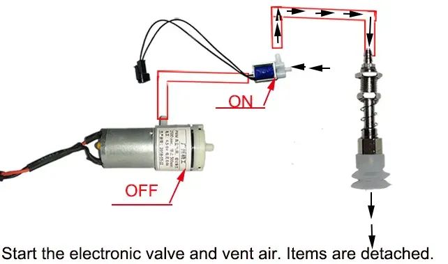
抽吸泵机构
-
将真空泵、继电器模块和电磁阀的负极端子连接到电源的负极端子。
-
将继电器模块的正极端子连接到电源的正极端子。
-
将继电器模块的信号线连接到 Arduino 板的数字引脚 3。
-
将真空泵的正极端子连接到继电器模块的常开 (NO) 端子。
-
将电磁阀的正极端子连接到继电器模块的常闭 (NC) 端子。
-
将继电器模块的公共端子连接到电源输入的正极端子。
-
Arduino代码:
-
设置和初始化库和变量。
#include <Servo.h>#include <Wire.h>
#include <Adafruit_PWMServoDriver.h>// called this way, it uses the default address 0x40
Adafruit_PWMServoDriver pwm = Adafruit_PWMServoDriver();#define USMIN  1000//600 // This is the rounded 'minimum' microsecond length based on the minimum pulse of 150
#define USMAX  2000//2400 // This is the rounded 'maximum' microsecond length based on the maximum pulse of 600
#define SERVO_FREQ 50 // Analog servos run at ~50 Hz updatesuint16_t Pos1;
uint16_t Pos2;
uint16_t Pos3;
uint16_t Pos0;int ang;int ang2;int ang3;int ang0;int X; //variable storing data from the index finger (landmark 8)int Y; //variable storing data from the middle finger(landmark 12)int Z; //variable storing data from the ring finger (landmark 16)int J; //variable storing data from the bottom of the palm (landmark 0)int K; //variable storing data from the thumb finger (landmark )int L; //variable storing data from the thumb finger (landmark )const int RELAY_PIN = 3; // auction pump relay pinconst int RELAY_PIN = 3;-
“setup”部分在通电后运行一次并定位伺服电机。
void setup() {Serial.begin(9600);Serial.println("Ready"); // prints ready on the serial portpinMode(RELAY_PIN, OUTPUT);  //setting relay pin to outputdigitalWrite(RELAY_PIN, LOW);  //putting off relay pinPos1 = 1500;Pos2 = 1500;Pos3 = 1500;Pos0 = 1500;pwm.begin();pwm.setOscillatorFrequency(27000000);pwm.setPWMFreq(SERVO_FREQ);  // Analog servos run at ~50 Hz updatesfor(int i = 0; i < 4; i++) {  // loop to position the servo motors in their initial state after startuppwm.writeMicroseconds(i, Pos1);delay(10);}
}-
关键组件是“postn”函数,它将“loop”函数中设置的变量转换为运动。它需要四个输入(A、B、C 和 D)
-
A是手掌上被跟踪以控制伺服电机的点,从计算机串行发送到Arduino,由“loop”函数读取。
-
该函数会验证伺服器的当前位置是否在其最小和最大限制范围内,然后根据它经过的触发器在任一方向上以 20 为增量进行调整。在界标 0(手腕/下手掌)处运行代码时,触发器 B 和 C 会显示在屏幕上。
-
B 和 C 是上/左和下/右触发器,当跟踪的手掌点穿过它们时,分别控制伺服运动的上/右或下/左。
-
“postn”函数的最后一部分根据手部地标 3 和 4 的位置打开和关闭抽吸泵。
void Postn()
{if ((X < 90) && (Pos1 > USMIN) && (Pos1 < USMAX)) // if the tracked landmark (stored as X) is lower than the lower trigger (90) and{ // and the current position (pos1) of the servo is greater than its minimum limit (usmin)Pos1 -= 20; //and the current position of the servo is less than its maximum limit (usmax)pwm.writeMicroseconds(1, Pos1); // the servo position moves in steps of 20Serial.print("X = "); // a signal is sent to the servo to effect the change in position (pos1)Serial.println(Pos1);if (Pos1 == USMIN) // if the variable storing the position of the servo gets to the min limit (servomax){Pos1 = USMIN + 20;} // the servo will get stuck; hence, this line reduces its value at the end of this section of the code. you can comment this line and run a test to better understand }if ((X > 150) && (Pos1 > USMIN) && (Pos1 < USMAX)) // if the tracked landmark (stored as X) is higher than the uppwer trigger (150) and{ // and the current position (pos1) of the servo is greater than its minimum limit (usmin)Pos1 += 20; //and the current position of the servo is less than its maximum limit (usmax)pwm.writeMicroseconds(1, Pos1); // a signal is sent to the servo to effect the change in position (pos1)Serial.print("X = ");Serial.println(Pos1);if (Pos1 == USMAX) // if the variable storing the position of the servo gets to the max limit (servomax){Pos1 = USMAX - 20;} // the servo will get stuck; hence, this line reduces its value at the end of this section of the code. you can comment this line and run a test to better understand }if ((Y < 70) && (Pos2 > USMIN) && (Pos2 < USMAX)) // the logic above applies to the here and for the lest of this function{Pos2 -= 20;pwm.writeMicroseconds(2, Pos2);Serial.print("Y = ");Serial.println(Pos2);if (Pos2 == USMIN){Pos2 = USMIN + 20;} }if ((Y > 130) && (Pos2 > USMIN) && (Pos2 < USMAX)){Pos2 += 20;pwm.writeMicroseconds(2, Pos2);Serial.print("Y = ");Serial.println(Pos2);if (Pos2 == USMAX){Pos2 = USMAX - 20;} }if ((Z < 70) && (Pos3 > USMIN) && (Pos3 < USMAX)){Pos3 += 20;pwm.writeMicroseconds(3, Pos3);Serial.print("Z = ");Serial.println(Pos3);if (Pos3 == USMAX){Pos3 = USMAX - 20;} }if ((Z > 130) && (Pos3 > USMIN) && (Pos3 < USMAX)){Pos3 -= 20;pwm.writeMicroseconds(3, Pos3);Serial.print("Z = ");Serial.println(Pos3);if (Pos3 == USMIN){Pos3 = USMIN + 20;} }if ((J < 220) && (Pos0 > USMIN) && (Pos0 < USMAX)){Pos0 += 20;pwm.writeMicroseconds(0, Pos0);Serial.print("J = ");Serial.println(Pos0);if (Pos0 == USMAX){Pos0 = USMAX - 20;} }if ((J > 370) && (Pos0 > USMIN) && (Pos0 < USMAX)){Pos0 -= 20;pwm.writeMicroseconds(0, Pos0);Serial.print("J = ");Serial.println(Pos0);if (Pos0 == USMIN){Pos0 = USMIN + 20;} }if (K > L) //The pump function checks if hand landmark 4 (tip of thumb) is to the right or left side { //of hand landmark 3 (IP joint), this in turn switches on and off the suction pump.digitalWrite(RELAY_PIN, LOW);Serial.print("K =");Serial.println(K);Serial.print("L =");Serial.println(L);}if (K < L){digitalWrite(RELAY_PIN, HIGH);Serial.print("K");Serial.println(K);Serial.print("L");Serial.println(L);}}-
“loop”函数检查串行端口是否有从计算机传输的数据,并相应地调用“postn”函数。
void loop() {// The 'loop' function checks the serial port for data being transmitted //from the computer; depending on the data it gets, it calls upon the 'postn' function.// or the pump functionif(Serial.available() > 0){if(Serial.read() == 'X'){X = Serial.parseInt();if(Serial.read() == 'Y'){Y = Serial.parseInt();if(Serial.read() == 'Z'){Z = Serial.parseInt();if(Serial.read() == 'J'){J = Serial.parseInt();if(Serial.read() == 'K'){K = Serial.parseInt();if(Serial.read() == 'L'){L = Serial.parseInt();Postn();}}}}}}}}-
python 脚本中的注释解释了你需要了解的所有内容。使用 PyCharm 打开 python 脚本并运行脚本。弹出一个新窗口,显示相机看到的内容,正确放置你的手,并移动适当的地标以使机器人手臂移动。
你可以在 Arduino IDE 上打开串行监视器以查看传输到 Arduino 的数据,但请确保在你想要重新启动 python 脚本时,关闭串行监视器以防止错误。
import cv2    #import neccesary libraries after adding them as packages to this project
import mediapipe as mp    # go to settings > python interpreter
import serial
import time
import mathArduino=serial.Serial('/dev/cu.usbmodem14101', 9600, timeout=0.1)  #initialize the serial port(in quotation marks) for communicatin with the arduinowCam, hCam = 1240, 720   # variable for setting the camera window width and height
cam = cv2.VideoCapture(0)  # start the webcam, use 0 for and inbuilt camera and 1 for an external one
cam.set(3, wCam)     #setting the camera window width and height
cam.set(4, hCam)
smoothV = 2
pVal = 0
cVal = 0color = (255, 255, 255)class mpHands:  #class used to detect hands, hand landmarks, measure distance and angle between hand landmarks# watche this video for an explanation of the class; https://www.youtube.com/watch?v=WQeoO7MI0Bs&t=8774sdef __init__(self, mode=False, modelComplexity=1, maxHands=2, TrackCon=0.5, DetectCon=0.5):self.mode = modeself.modelComplexity = modelComplexityself.maxHands = maxHandsself.TrackCon = TrackConself.DetCon = DetectConself.mpHands = mp.solutions.handsself.hands = self.mpHands.Hands(self.mode, self.maxHands, self.modelComplexity,self.TrackCon, self.DetCon)self.mpDraw = mp.solutions.drawing_utilsdef Marks(self,frame):myHands=[]handsType=[]frameRGB=cv2.cvtColor(frame,cv2.COLOR_BGR2RGB)results=self.hands.process(frameRGB)if results.multi_hand_landmarks != None:for hand in results.multi_handedness:#print(hand)#print(hand.classification)#print(hand.classification[0])handType=hand.classification[0].labelhandsType.append(handType)for handLandMarks in results.multi_hand_landmarks:myHand=[]for landMark in handLandMarks.landmark:h, w, c = frame.shapemyHand.append((int(landMark.x*w),int(landMark.y*h)))myHands.append(myHand)return myHands, handsTypedef findDistance(self, a, b, frame ):x1, y1 =a[0], a[1]x2, y2 =b[0], b[1]cx, cy = (x1 + x2) // 2, (y1 + y2) // 2  # center point between thumb and index fingercv2.circle(frame, (x1, y1), 5, (255, 255, 255), cv2.FILLED)  # circle on thumbcv2.circle(frame, (x2, y2), 5, (255, 255, 255), cv2.FILLED)  # circle on index fingercv2.circle(frame, (cx, cy), 5, (255, 255, 255), cv2.FILLED)  # circle at center point bte thumb and indexcv2.line(frame, (x1, y1), (x2, y2), (255, 255, 255), 3)  # line btw index and center pointlength = int(math.hypot(x2 - x1, y2 - y1))# print(length)return length, frame, [x1, y1, x2, y2, cx, cy]def findAngle(self, a, b, c, frame ):#get the landmarksx1, y1 = hand[a]x2, y2 = hand[b]x3, y3 = hand[c]#get the angleangle = math.degrees(math.atan2(y3-y2, x3-x2) - math.atan2(y1-y2, x1-x2))if angle<0:angle= angle+360return angle#print(angle)width=1280
height=720
findHands=mpHands(2)while True:ignore,  frames = cam.read()frame= cv2.flip(frames, 1) #fliping the camera output sideways, comment this line to see the differencehandData, handType = findHands.Marks(frame)for hand, handType in zip(handData, handType):right = 0left = 0if handType == 'Right':handColor = (0, 0, 255)#tracking landmark 0 located at the wrist (lower part of the palm)l1, l2 = hand[0]  # x and y coordinates for the point at the bottom of the palm (wrist)cv2.circle(frame, (l1, l2), 10, (0, 0, 255), cv2.FILLED)  # draw a red circle at the point# this point controlls the rotation of the base of the armcv2.line(frame, (50, l2), (220, l2), (46, 98, 84), 3)   #this lines draw a green, white and green line on the screencv2.line(frame, (220, l2), (370, l2), (255, 255, 255), 3)    #movement of landmark 0 to the green part of the line makes the armcv2.line(frame, (370, l2), (550, l2), (46, 98, 84), 3)          # rotate to the the left or right (when it crosses the limits triggers at the upper and lower points of the line (220 and 370 on the x axis respectively)cv2.circle(frame, (50, l2), 5, (255, 255, 255), cv2.FILLED)  #these lines draw a circle at the two ends of the gree, white and green linecv2.circle(frame, (550,l2), 5, (255, 255, 255), cv2.FILLED)  # they also draw circles at the two boundaries between the green and white linecv2.circle(frame, (220, l2), 5, (255, 255, 255), cv2.FILLED)cv2.circle(frame, (370, l2), 5, (255, 255, 255), cv2.FILLED)cv2.putText(frame, 'A', (l1,l2-50), cv2.FONT_HERSHEY_SIMPLEX,     # A is shown on the landmark being tracked0.5, color, 2)cv2.putText(frame, 'B', (220, l2+50), cv2.FONT_HERSHEY_SIMPLEX,0.5, color, 2)  # prints B at the location of the leftward triggerscv2.putText(frame, 'c', (370, l2 + 50), cv2.FONT_HERSHEY_SIMPLEX, 0.5, color, 2)  # prints B at the location of the rightward triggerscv2.putText(frame, 'servo 0', (280, l2 + 50), cv2.FONT_HERSHEY_SIMPLEX, 0.5, color, 2) # prints  the pin of servo being controlledif (51 <= l1 <= 499):   # the total length of the line created above is 448 (449-51) on the X axisJ = l1                 # if the landmark being tracked is between the range above then it is stored with the variable Jelif (l1 < 51):         # if the point being tracked (landmark 0) is at a position less than 51 on the X axis (the min point on the line drawn aboveJ = 51          #it is still stored as 51 because that is the lower limit and this being absent would result in errors when transferring data to the arduino( nothing will be sent to the arduino and the python script is coded such that something must be sent, thats why errors will come up)elif (l1 > 499):   # the same applies here with the upper limit of 499J = 499# tracking landmark 8 located at the tip of the index finger, this controlls the shoulder jointl1, l2 = hand[8]   # the same logic used to track landmark 0 applies herecv2.circle(frame, (l1, l2), 10, (0, 0, 255), cv2.FILLED)cv2.line(frame, (l1, 20), (l1, 90), (46, 98, 84), 3)cv2.line(frame, (l1, 90), (l1, 150), (255, 255, 255), 3)cv2.line(frame, (l1, 150), (l1, 220), (46, 98, 84), 3)cv2.circle(frame, (l1, 20), 5, (255, 255, 255), cv2.FILLED)cv2.circle(frame, (l1, 220), 5, (255, 255, 255), cv2.FILLED)cv2.circle(frame, (l1, 90), 5, (255, 255, 255), cv2.FILLED)cv2.circle(frame, (l1, 150), 5, (255, 255, 255), cv2.FILLED)if (21 <= l2 <= 219):X = l2elif (l2 < 21):X = 21elif (l2 > 179):X = 179# tracking landmark 12 located at the tip of the middle finger, this controlls the elbow jointl1, l2 = hand[12]    # the same logic used to track landmark 0 applies herecv2.circle(frame, (l1, l2), 10, (0, 0, 255), cv2.FILLED)cv2.line(frame, (l1, 20), (l1, 70), (46, 98, 84), 3)cv2.line(frame, (l1, 70), (l1, 130), (255, 255, 255), 3)cv2.line(frame, (l1, 130), (l1, 180), (46, 98, 84), 3)cv2.circle(frame, (l1, 20), 5, (255, 255, 255), cv2.FILLED)cv2.circle(frame, (l1, 180), 5, (255, 255, 255), cv2.FILLED)cv2.circle(frame, (l1, 70), 5, (255, 255, 255), cv2.FILLED)cv2.circle(frame, (l1, 130), 5, (255, 255, 255), cv2.FILLED)if (21 <= l2 <= 179):Y = l2elif (l2 < 21):Y = 21elif (l2 > 179):Y = 179# tracking landmark 16 located at the tip of the ring finger, this controlls the wrist jointl1, l2 = hand[16]    # the same logic used to track landmark 0 applies herecv2.circle(frame, (l1, l2), 10, (0, 0, 255), cv2.FILLED)cv2.line(frame, (l1, 20), (l1, 70), (46, 98, 84), 3)cv2.line(frame, (l1, 70), (l1, 130), (255, 255, 255), 3)cv2.line(frame, (l1, 130), (l1, 180), (46, 98, 84), 3)cv2.circle(frame, (l1, 20), 5, (255, 255, 255), cv2.FILLED)cv2.circle(frame, (l1, 180), 5, (255, 255, 255), cv2.FILLED)cv2.circle(frame, (l1, 70), 5, (255, 255, 255), cv2.FILLED)cv2.circle(frame, (l1, 130), 5, (255, 255, 255), cv2.FILLED)if (21 <= l2 <= 179):Z = l2elif (l2 < 21):Z = 21elif (l2 > 179):Z = 179# this part id used to controll the suction pump. the suction pump is switched on or off depending on weather the tip of the thumb is positioned# at he left or right of the joint below the tip of the thumbl1, l2 = hand[4]   #this represents the X and Y coordinated of tip of the thumbl3, l4 = hand[3]   #this represents the X and Y coordinated of joint below the tip of the thumbcv2.circle(frame, (l1, l2), 10, color, cv2.FILLED)  #this draws a circle at landmark 4, color was decleared in line 17cv2.line(frame, (l3, l4+20), (l3, l4-100), (255, 255, 255), 3)   #draws a white vertical line at landmark 3#cv2.line(frame, (65, l2), (80, l2), (255, 0, 0), 3)cv2.circle(frame, (l3, l4+20), 5, (255, 255, 255), cv2.FILLED)   # draws circles at the two ends of the line drawn abovecv2.circle(frame, (l3, l4-100), 5, (255, 255, 255), cv2.FILLED)#cv2.circle(frame, (80, l2), 5, (255, 255, 255), cv2.FILLED)K = l1L = l3if ( l1 < l3):   # the color of the circle at the tip of the thumb changes to red or greencolor = (46, 98, 84)   # depending on its position (to the right or left of the joint below the thumb (landmark 3))elif (l1 > l3):           # this signifies weather the pupmp is powered on or offcolor = (0, 0, 255)values = 'X{0}Y{1}Z{2}J{3}K{4}L{5}'.format(X, Y, Z, J, K, L)   # all the variables used to store data are hereArduino.write(values.encode('utf-8'))    # the data containing the position of the landmarks being tracked are sent to the arduinoprint(values)  # the data being transferred is displayedcv2.imshow('my WEBcam', frame)#cv2.moveWindow('my WEBcam',0,0)if cv2.waitKey(1) & 0xff ==ord('q'):   # press the Q button on the keyboard to stop the camerabreak
完成后,手的演示视频:https://youtu.be/XSMEVKlM3js
现在就这些了,你可以随时改进这个项目的伺服电机,并调整代码。此外,可以嵌入深度视觉相机,通过跟踪整个手指,而不是一个手指的运动,来更精确地控制手臂手指上的单个地标。
☆ END ☆
如果看到这里,说明你喜欢这篇文章,请转发、点赞。微信搜索「uncle_pn」,欢迎添加小编微信「 woshicver」,每日朋友圈更新一篇高质量博文。
↓扫描二维码添加小编↓
